Team:KCL UK/Contribution
Contribution
A Guide to Bioprinting by Renervate:
Renervate, King’s College London’s iGEM team, identified a gap in the market where spinal cord injuries were primarily left untreated, forcing individuals to learn how to adapt to a life with injury. The limited success rate in treating the primary injury of spinal cord injuries encouraged us to look into different novel approaches and investigate how we could use synthetic biology in order to resolve this harrowing issue.
When choosing a project title it is essential your team is both passionate and challenged by the subject area - there needs to be a strong drive to resolve an issue close to your hearts. Not only do spinal cord injuries alter an individual’s life but the current treatments present on the market do not provide a comprehensive treatment. Treatments such as immobilisation, intravenous (IV) Methylprednisolone Sodium Succinate (MPSS) and surgical compression all focus on the acute phase of spinal cord injuries. This means the formation of the glial scar at the chronic phase is not targeted even though after treating the acute and sub acute phase the formation of the cavity can still persist. Henceforth, our team decided it was crucial to provide a solution to minimising the trauma induced by the chronic phase by reducing axonal die-back by providing a bridge for axons to regenerate.
In order to achieve this we used a 3D bioprinted scaffold because it offers a customisable approach where we can adapt our scaffold design for each patient’s spinal cord injury geometry, ultimately providing a more inclusive treatment. This guide provides a comprehensive outlook on how you can develop a biocompatible scaffold to treat different injuries.
Scaffold Specification Sheet
When designing a scaffold you must consider the following features shown in the diagram below:

You can adjust the criteria for these to suit your project. It is to your discretion which requirements you prioritise the most as it is unfeasible to achieve all of them.
Selecting a bioink
Your choice of bioink will have specific properties. For example, its viscosity will affect which bioprinters you will be able to use. There are many different bioinks to choose from: matrix, sacrificial, and support bioinks.
| Type of Ink | Description |
|---|---|
| Matrix | Hold and support cells. Most are hydrogels. |
| Sacrificial | These are used for temporary implants. |
| Support | These are biocompatible and have much better mechanical properties than matrix inks. |
Natural Vs. Synthetic Polymers for Bioinks
| Natural | Synthetic |
|---|---|
| Higher biological activity | Better Mechanical Strength |
| Most are biocompatible | Higher Machinability |
| Maintains the structural integrity of the ECM | More controllable degradation rates |
| Examples: Chitosan, Collagen, Alginate. | Examples: PCL, PLA, PLGA. |
Macro and Micro architecture
Generating 3D Models
The Porosifier
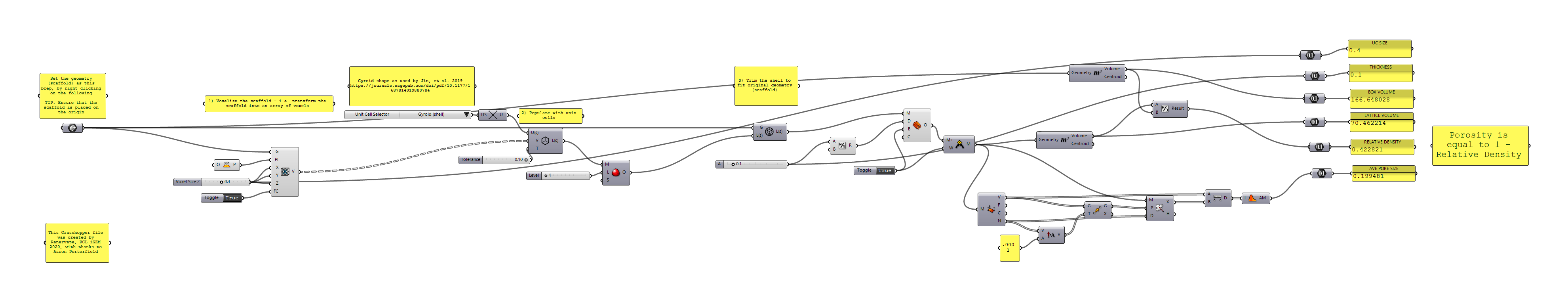
At the beginning of the computational implementation stage of the microarchitecture design for the scaffold, we found there to be a scarcity of software that could implement our desired topography with relative ease. The initial software that we utilised to design the macro-architecture of our scaffold, Autodesk Inventor, was not sufficient to create such small-scale features (~200μm); therefore, we resulted to using Rhinoceros with the Grasshopper plugin. Grasshopper 3D is a visual programming language that allows for the coding of algorithms that govern the design of a given CAD object in the Rhinoceros environment. Within this software, we created a program, we called The Porosifier that produces a porous architecture on any given 3D structure - a visual representation of this is depicted in Fig. 1.

This added porosity is entirely personalisable; the Grasshopper script contains sliders that allow for the adjustment of pore size and porosity of the object – via the customisation possibilities, such as changing the unit cell type, the cell size and cell thickness. This is not only useful for scaffold implementation, but for other applications that require the creation of a porous structure – such as other medical device implants. Moreover, it allows for future testing of different porosities within scaffold design, without the need for a tedious redesign process – you can merely adjust the sliders and the algorithm generates the new porous design. The Grasshopper file can be downloaded here – of which contains comments within to help a user understand its methodology and usage (as seen below in Fig. 2) - open for use within further research and projects. You can find our application of The Porosifier here, as well as some background information about the process that the algorithm follows.
Conceptual Depiction of The Porosifier
Macroarchitecture Design Process
- You can use AutoCAD or Autodesk Inventor to design your scaffolds as these are free with an educational license.
- The official documentation contains helpful tutorials in designing.
- Below are CAD drawings of our scaffolds:
We used proposed designs from literature and used this as a primary source of influence in our scaffold design. We used the available tools in Autodesk to design them. Using the NASTRAN extension we conducted non-linear stress analysis. This allows you to conduct tests by applying different loads on your structure. E.g. forces, pressures, moments, gravity, rotational forces and bearing loads. Conducting these tests will allow you to produce results showing the stress, strain, applied force, and displacements on the structure, giving you a better indication how it will perform.

Simulation
To simulate the scaffolds we used the Inventor extension, NASTRAN. We ran a non-linear stress analysis.
How to Personalise your Scaffold
This video is a tutorial on how to segment a patient MRI/CT scan of the region of interest. With a segmented scan you have information regarding the shape and size of your region of interest. We have made our treatment personalised using this method, by adjusting the scaffold to the dimensions of the patient's cyst.
Degradation Modelling
A large aspect of the design consideration was the biodegradability of our scaffold, being one of the core parts of our scaffold specification sheet. However, unfortunately, we did not have access to the labs to validate any parameters affecting degradation rate – hence we could not test how initial molecular weight or porosity would change how rapidly our scaffold degraded.
To overcome this issue, after carrying out an extensive literature review, we created our own MATLAB program to simulate the degradation of a polymer scaffold in vivo – as we could not identify a similar software to carry this out. Our program allows the user to find the prediction of degradation over time based on a known degradation rate or scaffold porosity (given that the material is PCL for the latter). The calculation for degradation as a result on porosity is based on experimental data obtained by (Zhang et al., 2013) specific to polycaprolactone. However, if the user wishes to test another polymer scaffold’s degradation they may – if they know a specific degradation rate. There is the potential, nevertheless, for the code to be modified, such that the porosity mathematical relation is changed to fit another polymer. This known degradation rate can be input with respect to any time frame (per hour, per week, per month) as our program can accommodate for unit conversions.
Moreover, it allows the user to enter the critical molecular weight (the limit of useful molecular weight) so that a warning dialogue can be displayed if their chosen design will decay too much in a specified time frame. If the initial molecular weight is unknown, there is also an option to find a suitable minimum initial molecular weight, providing that the duration that the scaffold must last, as well as a critical molecular weight and degradation rate/porosity is given to the program. We have made this program open-source, to allow for further experimentation regarding scaffold degradation - and it could further be adapted or applied to other polymers. The code can be found here, and the background of the mathematics behind it, as well as our chosen application of the program, can be found here.
As an example of degradation simulation for another polymer, here is the degradation prediction for a PLGA (another commonly used material) scaffold – using a degradation rate of 1.9e-3 hr-1, an initial molecular weight of 24.6kDa and a critical molecular weight of 1.2kDa (Hoque, 2012). The scaffold has been simulated over a specified time frame of one year, and as depicted, the implant would not last long enough in vivo, so a warning is shown to the user.


As a further customisation tool, the number of calculations computed for the degradation at varying time, t, can be inputted - allowing for a 'smoother curve' (though this is a trade-off between computational power and the number of calculations).
Printing Process

When picking a bioprinter you must pay attention to the resolution as this will decide what size you will be able to print the scaffold. It will mostly affect the microarchitecture.
The first step is to have your scaffold or medical implant design saved as an STL file. This is then converted into gcode by software such as CURA, which the 3D bio printer / 3D printer can now read and use to make movements in the motor.
Printing Parameters
The biomaterial / bioink that you use will require different settings. Parameters that you can change are nozzle size, printing speed, and layer height. For example, if you are using a thick bioink you will need to accommodate for this by lowering the printing speed. Resolution can be affected by the nozzle size (diameter of nozzle size). Temperature will need to be adjusted for the type of bioink you are using. The table below from Allevi3d shows the printing parameter and needle type required for common bioinks.


MFP Contribution
After identifying that our scaffold requires a mechanism to adhere in the spinal cord injury site, our team began to look into the use of a bio-adhesive alongside the scaffold to secure it within the SCI site and ensure that axon growth can occur without any further damage from movement. Here we document all the contributions we have made to the iGEM and greater scientific community, as well as the potential future applications of our project.
Documentation to Parts
A list of our parts can be found here, but a table of our parts can also be found below:
| Part Name | Part Number | Type | Description | Designer | Length |
|---|---|---|---|---|---|
| T7 Promoter | BBa_K3635004 | Basic | T7 promoter Coding sequence | Emily Blundell | 19 bp |
| Ribosome Binding Site | J61101 | Basic | RBS Sequence | John Anderson | 26 bp |
| Lac Operator | BBa_K3635003 | Basic | Lac Operator Sequence | Emily Blundell | 25 bp |
| Histidine Tag | BBa_K3635005 | Basic | 7xHis Tag | Emily Blundell | 21 bp |
| pBluescript II SK+ f1 Ori | BBa_K3635006 | Basic | Origin of Replication | Emily Blundell | 306 bp |
| Ampicillin Resistance | BBa_K3635007 | Basic | AmpR | Emily Blundell | 966 bp |
| Pvfp-5β Coding Sequence | BBa_K3635000 | Basic | Pvfp-5β Insert | Emily Blundell/Abigail Conner | 528 bp |
| Tyrosinase Coding Sequence | BBa_K3033013 | Coding | Tyrosinase Insert | Philip Naderev P.Lagniton | 891 bp |
| Renervate Plasmid Backbone | BBa_K3635008 | Composite | T7 promoter+RBS+lac operator+7xhis-tag+pBluescript II SK+ f1 ori+AmpR | Emily Blundell | 2219 bp |
| Pvfp-5β Expression Vector | BBa_K3635009 | Composite | T7 promoter+RBS+lac operator+Pvfp-5β+7xhis-tag+pBluescript II SK+ f1 ori+AmpR | Emily Blundell | 2755 bp |
| Tyrosinase Expression Vector | BBa_K3635013 | Composite | T7 promoter+RBS+lac operator+Tyrosinase+7xhis-tag+pBluescript II SK+ f1 ori+AmpR | Emily Blundell | 3116 bp |
Our contributions to parts introduce Pvfp-5β as a basic part, along with a suitable expression vector for expression in E.coli and an expression vector for our polymerisation strategy, utilising tyrosinase enzymes (see below). We encourage other teams to use and improve upon our parts, making changes where they see appropriate.
Improvement of Previous Parts
As we were unable to gain lab access this year, we are unable to provide experimental evidence for the improvement of previous parts. As a result, we have turned to literature to provide evidence for our claims.
We have based our parts mostly upon team Great Bay SCIE's parts, who also focused on producing an MFP-based adhesive, which can be found here.
We have also made note of team Yale 2014, which also produced an MFP based adhesive. Despite their project not being focused towards therapeutics, we still deemed it important in shaping our project. Their project information can be found here, and the relevant part on the registry.
Improvements to Great Bay SCIE 2019
1. Pvfp-5β
Great Bay SCIE 2019 used MFP-5 from Mytilus galloprovincialis. This was used to synthesise an underwater adhesive, alongside other adhesive proteins (see here).
In our project, we have used Pvfp-5 and Pvfp-5β as the main adhesive in our project. Research has strongly suggested the significant adhesive properties of this protein in comparison to its other Pvfp counterparts, as well other MFP’s across mussel species (Santonocito et al. 2019, Patil et al. 2018, Petrone et al. 2015, Lu et al. 2013). Therefore, as an improvement of their project, we have changed MFP-5 for Pvfp-5β, with the hopes to improve the adhesiveness of our adhesive for applications within SCI, as well as other biotechnology and therapeutic applications.
On top of this, we will only be using Pvfp-5, with no combinations of other adhesive proteins from other organisms. This is for multiple reasons:
- By using multiple adhesive proteins, we would have split the work force further in order to understand new adhesion mechanisms, which in turn would bring about new barriers to overcome. With our team already divided into three sub-teams, it would have significantly reduced the quality of our bio-adhesive polymer research and development.
- As we are applying our bio-adhesive as a therapeutic agent, we would need to consider the immunogenicity of the bio-adhesive. We increase the potential for an immune reaction in patients by adding more “antigens” for the body to respond too.
- Using multiple proteins alongside each other opens the potential for “conflict” between proteins, all of which will have different optimal conditions. This is an especially important consideration as we will be applying our bio-adhesive within the spinal cord, which has a very complex microenvironment (Fan et al., 2018). Balancing the requirements for each protein for optimal adhesion will increase the complexity of the adhesive, and overcomplicate the adhesion mechanism.
2. Tyrosinase
In order to polymerise our protein, we have decided to use tyrosinase to polymerise our protein, in place of the Csga method used by Great Bay SCIE last year. Tyrosinase mimics the reaction pathway of mussel byssal tanning and mussel sclerotization where the DOPA residues oxidise into DOPA-quinone and form cysteinyl-DOPA bonds with itself and neighbouring mussel foot proteins; thereby adding another degree of biomimicry to our project (Burzio et al., 2000). Furthermore, tyrosinase has also previously been used to polymerise mussel foot proteins in situ whereas other approaches to polymerise mussel foot proteins (such as in vitro methods) has resulted in the aggregation of the protein into inclusion bodies and rendered them functionless (Choi et al., 2012). Polymers created using these methods have been able to effectively coat significantly different surfaces and are tolerant to harsh conditions, features that are associated with mussel foot proteins therefore suggesting that this method of polymerisation does not impair protein function. Additionally, the remaining un-crosslinked dopaquinone in the extracted polymer can be reduced back to DOPA by using an antioxidant; this has been previously used and shown to improve adhesion of the mussel foot protein polymer (Horsch et al., 2018). One of the issues team Great Bay SCIE stated last year was their difficulty in producing significant product yield. Using our method, we hope to improve upon this aspect of their project, which we will test in the lab. Lastly, by using Pvfp-5β as an ADHESIVE and COHESIVE, we greatly simplify our BioBricks, as well as applications in vivo.
Improvements to Yale 2014
1. Tyrosinase
In place of using a genetically recoded organism (GRO) to synthesise DOPA residues, we are using a tyrosinase co-expression system to convert tyrosine residues into DOPA to "activate" adhesion in our MFP. We have made this decision based on the same reasons above. On top of this, we will be converting our protein into a polymer, which will improve the structural integrity of our bio-adhesive, as well as improve our polymers adhesive capabilities. This was an implication we made after consulting Professor Pastore and Dr Aflano (see Attributions).
Proposed implementation
Throughout the project we have documented a variety of ideas, research and information for future teams to build upon. Many of these ideas were not implemented in order to simplify our project, comply with time constraints, or because we were unable to gain lab access. We encourage future teams to build upon our work where they see potential for improvement. Here, we list the research we have done which can be utilised by other teams:
| Research Subject | Potential uses |
|---|---|
| Prevention of Oxidation | Our team has looked into several ways of reducing the potential for the oxidation of DOPA into DOPA-quinone at physiological pH. We have decided to implement boronate complexes after consulting with Dr. Petrone (see Attributions), however, there remains a high potential for the use of iron chelation, Pvfp-6, chlorination, as well as optimising the inherent anti-oxidative properties of MFP’s. The information can be found here. |
| Streptavidin and PCL Binding | Our team considered the use of streptavidin to both provide strong adhesion between MFP and PCL, as well as a method of purification in a streptavidin-biotin affinity purification. This would be mediated by an EDC/NHS coupling mechanism. We encourage teams with lab access to use this research to potentially find an effective way to ensure MFP adhesion to PCL. |
| Polymerisation | We plan to polymerise Pvfp-5β with a tyrosinase mediated polymerisation method. The other method of polymerisation we have researched is bidentate/tridentate iron chelation. We believe this has high potential, especially because of the self-healing properties it shows, suitable for the mobile environment of the spine. The information can be found here. |
| Extracellular Matrix Derivatives | ECM proteins and derivatives of ECM proteins have been used in many different tissue engineering applications, including those for polymer scaffolds. These include laminin, fibronectin and vitronectin, and ECM derivatives like RGD (Arg-Gly-Asp) and IKVAV (Ile‐Lys‐Val-Ala‐Val) [1],[6]. RGD is a peptide sequence abundant in several ECM proteins [3], and has been shown to improve cell adhesion and proliferation across multiple studies [2],[3], including nervous tissues [4]. This peptide sequence interacts with surface integrin receptors of cells, including the growth cone of propagating axons, as well as glial cells [5]. Despite these benefits, ECM protein derivatives can be immunogenic, and so we decided against implementing them until we are able to obtain lab access to test the immunogenicity of our polymer before and after adding these derivatives. We encourage teams to further this research. |
Contributions to Greater Science
There is a large section of the scientific community researching wet adhesives, specifically those utilising mussel foot proteins including both therapeutic and biotechnological applications. For these fields in particular, our research will have been a significant contribution, culminating a variety of information from literature, as well as presenting our ideas, techniques and approaches to producing a bio-adhesive for therapeutic purposes. On top of this, our structural model and WebServer results can be used by others for their own research purposes. Our project opens up many potential applications for our bio-adhesive in not only other therapeutic applications, but also for applications in bioengineering and other technology directed for aqueous environments. We hope our project will provide a significant contribution to other iGEM teams, as well as other researchers outside of the iGEM competition.
Protocols
Our protocols are open for other teams to use and adapt in their respective projects. These can be found on our Proposed Implemenation and Engineering pages.
Modelling
We welcome other teams to use our structural model to aid their own projects. We have set up the R programme iGAM with the aid of Andrew Symes (see here) to function with our protein, minus a fitness function. We encourage teams to use this to adapt our protein to their respective projects, by producing a fitness function from their experimentation.
Entrepreneurship
As a part of producing a therapeutic product, we have created a plan to direct our product to the marketplace. This is especially important consideration, as therapeutic products must undergo thorough regulation in order to reach the marketplace. The details of this can be found on our Entrepreneurship page. Through our research in entrepreneurship, we have thoroughly enjoyed the opportunity to explore the necessary steps we would need to take to commercial our product. We have condensed all we have learnt into a general guide for other iGEM teams in planning the commercialisation of their projects, shown below.

We hope this guide will help future teams in their journey to producing a viable product.
Biologix
As a addition to the inclusivity award, our team have put together Biologix, a free competition designed by us in order to engage students in STEM related careers, as well as providing the key skills and foundations for iGEM once students reach university, providing the experience needed for personal statements. We encourage teams to spread the awareness of the competition, as well as look for future collaborations with us to create new resources for the competition. We have outlined the details of how we plan to run the competition, and we encourage teams to host the competition to their local schools to raise the awareness of the competition.
References for Bioprinting
- Allevi. 2020. Bioprinting Parameters For Every Bioink Cheat Sheet | Support - Allevi. [online] Available at:
- Hoque, M., Yong, L. and Ian, P. (2012) ‘MATHEMATICAL MODELING ON DEGRADATION OF 3D TISSUE ENGINEERING SCAFFOLD MATERIALS’, Official Journal of Tissue Engineering and Regenerative Medicine Society of Malaysia, 1(1), pp. 58–61.
- Paul A. Yushkevich, Joseph Piven, Heather Cody Hazlett, Rachel Gimpel Smith, Sean Ho, James C. Gee, and Guido Gerig. User-guided 3D active contour segmentation of anatomical structures: Significantly improved efficiency and reliability. Neuroimage 2006 Jul 1;31(3):1116-28.
- Zhang, Q., Jiang, Y., Zhang, Y., Ye, Z., Tan, W. and Lang, M., 2013. Effect of porosity on long-term degradation of poly (ε-caprolactone) scaffolds and their cellular response. Polymer Degradation and Stability, 98(1), pp.209-218.
References for MFP Contribution
- Burzio L, A., Burzio V, A., Pardo, J. and Burzio L, O. 2000. In Vitro polymerization of mussel polyphenolic proteins catalyzed by mushroom tyrosinase. Comparative Biochemistry and Physiology, (126), 383-389.
- Choi Y, S., Yang Y, J., Yang, B. et al. 2012. In vivo modification of tyrosine residues in recombinant mussel adhesive protein by tyrosinase co-expression in Escherichia coli. Microb Cell Fact 11, 139.
- Fan, B., Wei, Z., Yao, X., Shi, G., Cheng, X., Zhou, X., Zhou, H., Ning, G., Kong, X., and Feng, S. (2018). Microenvironment Imbalance of Spinal Cord Injury. Cell transplantation, 27(6), 853–866.
- Horsch, J. Wilke, P. Pretzler, M. Seuss, M. Melnyk, I. Remmler, D. Fery, A. Rompel, A and Börner G, H. 2018. Polymerizing like mussels do: toward synthetic mussel foot proteins and resistant glues. Angew Chem Int Ed, 57(14), 15728-15732.
- Lu, Q,. Danner, E,. Waite J, H,. Israelachvili J, N., Zeng, H. and Hwang D, S. 2013. Adhesion of mussel foot proteins to different substrate surfaces. J R Soc Interface 10:20120759.
- Patil, N. J., Vinueza Naranjo, P. G., and Zappone, B. 2018. Propiedades Adhesivas Húmedas de la Proteína del Pie de Mejillones Verdes Asiático (Perna viridis) Pvfp-5: Una Base Adhesiva Subacuática. NOVASINERGIA, ISSN 2631-2654, 1(2), 90-99.
- Petrone, L., Kumar, A., Sutanto, C., et al. 2015. Mussel adhesion is dictated by time-regulated secretion and molecular conformation of mussel adhesive proteins. Nat Commun 6, 8737.
- Santonocito, R., Venturella, F., Fabrizio D, F., Morando A, M., Passantino, R., Pastore, A., Biagio, Provenzano, A., Rao, E., Costa A, M., Bulone, D., Luigi, P., Biagio, S., Giacomazza, D., Alessandro, S. and Alfano, C., 2019. Recombinant mussel protein Pvfp-5β: A potential tissue bioadhesive. J. Biol. Chem, 294:12826-12835.
References for ECM Derivatives
- [1] Wang, Y., Tan, H. & Hui, X. 2018, "Biomaterial Scaffolds in Regenerative Therapy of the Central Nervous System", BioMed Research International, vol. 2018, pp. 19.
- [2] Hong M, J., Kim J, B., Shim J., Kang S, K., Kim K,. Rhie W, J., Cha J, H. and Cho, D. 2012. Enhancement of bone regeneration through facile surface functionalization of solid freeform fabrication-based three-dimensional scaffolds using mussel adhesive proteins. Acta Biomaterialia, 8(7), 2578-2586.
- [3] Cui Z, F., Tian M, W., Hou P, S., Xu Y, Q. and Lee, I. 2006. Hyaluronic acid hydrogel immobilized with RGD peptides for brain tissue engineering. J Mater Sci: Mater Med. 17:1393–1401.
- [4] Paul M. Yip, Xiaoning Zhao, Anthony M.P. Montgomery, and Chi-Hung Siu. 1998. The Arg-Gly-Asp Motif in the Cell Adhesion Molecule L1 Promotes Neurite Outgrowth via Interaction with the αvβ3 Integrin. Molecular Biology of the Cell, 9(2), 277-290
- [5] Woerly, S., Pinet, E., Robertis, L., Van Diep V, D. and Bousmina, M. 2001. Spinal cord repair with PHPMA hydrogel containing RGD peptides (NeuroGel™). Biomaterials, 22(10), 1095-1111.
- [6] Wei, Yueteng & Tian, Weiming & Yu, Xing & Cui, Fu-Zhai & Hou, S & Xu, Qunyuan & Lee, In-Seop. 2007. Hyaluronic acid hydrogels with IKVAV peptides for tissue repair and axonal regeneration in an injured rat brain. Biomedical materials (Bristol, England). 2. S142-6.


