Team:Calgary/Randys Cell
 Overview
Inspiration
Understanding the Problem
Research and Ideation
Results and Challenges
Impact
References
OVERVIEW

Supporting VAD mitigation through testing
To tackle the lack of data, we devised a diagnostic test to indicate vitamin A deficiency. This season, we constructed an impedance measurement device, and verified its ability to measure impedance, which will be used as the method to quantify levels of retinol binding protein in the blood.
INSPIRATION
Why did we do it?
We learned from Dr. Charles Mather that there was difficulty obtaining data on Vitamin A, and further consulted Banda Ndiaye, who indicated that decision makers needed more data for intervention. We also learned from Dr. Sanou Dia, that a portion of data on VAD is based on coverage and not diagnosis. Inspired by low-cost, electrochemical detection circuits, the Randle Cell Circuit was born. To help illuminate the true scope of vitamin A deficiency, this attempts to make VAD testing more accessible.
UNDERSTANDING THE PROBLEM
Developing a diagnostic test appeared to be a daunting task… and
definitely was. We began by investigating current methods used to
diagnose Vitamin A deficiency. It turned out that it was largely
based upon clinical signs. In addition, Dr. Sanou Dia, a public
health nutritionist, explained that much of vitamin A data was
based upon vitamin A coverage rather than actually testing for it.
Diagnostic tests already exist, with varying utility. Taking
samples of a liver to observe levels of vitamin A are considered
gold standard but this measure is not feasible for population
evaluation. Serum retinol and breast milk retinol are also
indicators of vitamin A deficiency, but fail to consider liver
reserves of the micronutrient. ( Tanumihardjo, 2012). One of the
most prevalent methods is the modified relative dose response test
(MRDR). Since vitamin A is stored in the liver, a single blood
test is not indicative of vitamin A deficiency. The MRDR attempts
to bypass this limitation by administering a test dose of a form
of retinol to elicit a response from the liver. This biological
response is then compared to the initial test dose by taking a
blood sample, which can then elucidate the liver reserves of
Vitamin A, and ultimately, vitamin A deficiency. However, a major
barrier to making the MRDR more accessible is the need for
expensive, bulky laboratory equipment to quantify vitamin A. This
introduces the need for cold chain storage and transportation to
labs, drastically increasing the cost. This highlighted the need
for a method that is capable of measuring vitamin A deficiency
that is both inexpensive and offers rapid results. We consulted
Banda Ndiaye, the Deputy Regional Director Health, Africa, to see
what programs were in place to measure VAD, and also determine if
new methods were needed. He stressed that decision makers needed
more data to inform intervention. To learn about typical methods
of vitamin A measurement in Western medicine, we consulted Dr.
Christopher Naugler, an expert in pathology informatics. He
informed us that Vitamin A measurement is typically done after a
10 hour fast using a mass spectroscopy methodology. Ultimately,
Vitamin A testing is an expensive and long process, requiring cold
chain storage, especially when the procurement of a blood sample
is done far from the lab.
Given the practicality of the MRDR, we based our device on the
same working principle as the MRDR. We administer a test dosage,
and then retrieve a blood sample 2-4 hours later. However, to
bypass the requirement of expensive lab analysis and the cold
chain storage, the Randle Cell Testing Device uses impedance-based
analysis.
RESEARCH AND IDEATE
Coming Up With an Idea
Through consulting Dr. Colin Dalton, a microfabrication expert, we quickly realized that this project’s scope required two years to complete. He drove home the need for accuracy, precision and reliability, which would require thoroughly vetting a sensor design. We looked at different types of biosensors to solve this problem. Mechanical cantilever-based sensors appeared attractive given their high sensitivity and versatility. However, we focused on impedance based biosensors due to their low cost, high sensitivity and in some cases high selectivity. Vitamin A has a binding protein, known as RBP. Retinol, outside of the liver in the blood, is found in a 1:1 complex with RBP (Sommer, 2001). An aptamer-based method appeared to be a solution by which we could extract retinol binding protein from the blood. Thomas Lijnse, a PhD student at the University of Calgary, provided guidance on how one can make an aptamer-based test that uses impedance to quantify a protein. By using an electrode coated with aptamers, one can quantify the amount of protein bound by the aptamers by measuring the change in impedance. With a two year timeline, we largely focused our efforts this season on developing a circuit capable of detecting changes in impedance.
Sensitivity of the Device
We needed to determine constraints on our design, and specifically, how sensitive our diagnostic device had to be. The WHO defines vitamin A deficiency (VAD) by serum retinol concentrations less than 0.70µmol/L (Whitehead et al., 2015). We found that serum retinol is the best established biochemical indicator of vitamin A status (De Pee & Dary, 2002). Our first motive was to develop a model to calculate how much impedance change RBP could cause, and thus indicate how sensitive our biosensor had to be. However, speaking with Dr. Colin Dalton, he informed us that this was a very complex phenomena to model. We were informed that many of these types of biosensor were empirically based. Without laboratory access, we relied upon literature. Using a similar method of impedance analysis of an electrochemical cell, a biosensor for RBP was able to detect quantities of RBP as low as 2.5 ag/mL (Şimşek et al., 2014). Using values of frequency and input waveforms from this paper, we were able to define constraints needed to achieve similar sensitivity.
Selectivity
Whole blood samples taken from a finger prick were an ideal candidate, but this raised questions about how we could separate the plasma from serum and quantify levels of RBP. Thus, we consulted Sultan Khetani, a PhD student with extensive experience in biosensor design. He informed us that depending on how the method used to select an aptamer, known as SELEX, was carried out, the aptamer could be specific enough to select RBP from whole blood samples. In theory, if an aptamer is selective enough, it could be used for selecting RBP from whole blood samples. Robert Mayall from FREDsense informed us that a common issue with using impedance based testing on blood, is fouling of the electrode. We were able to find an aptamer sequence in literature that was proven to be selective in human serum. Lab data and further aptamer research is needed to determine whether or not separation of plasma from serum will be necessary.
How it Works
Impedance is different from resistance in that it describes the sum of both the resistance and reactance. Systems, outside of conventional circuitry, can be described using combinations of impedances. The Randle's Circuit is a common equivalent circuit used to model electrochemical cells, and is described in Figure 1.

Figure 1 Equivalent Randle's Circuit of an Electrochemical Cell
In the diagram above, Zw is a warburg impedance. This models the slow diffusion process, something that is difficult to model with a simple differential equation. Zw can be modelled as:
Equation 1:

Equation 2:

The Cdl is known as the double layer capacitance, and models the effect of charges building up in the electrolyte on the electrode surface. Rct is the charge transfer resistance, accounting for voltage drop over the electrode-electrolyte interface due to a load. Lastly, Rs models the electrolyte resistance. Equation 3.0 is the impedance of a capacitor, and can thus be used to model the impedance of the double layer capacitance.
Equation 3:

The working principle of the Randle Cell Testing Device is the perturbation of the double layer capacitance in Figure 1 caused by the binding of RBP. This perturbation of Cdl has been known to cause significant changes in impedance. This change has been most noticeable at lower frequencies, less than 10kHz (Venkatraman et al., 2009). In addition, at low frequencies, the warburg impedance acts like a resistor (Lim, 2014). Notice that in Equation 2.0, the magnitude of the warburg impedance is directly proportional to the inverse of the square root of frequency. Therefore, as frequency approaches 0, the warburg impedance becomes infinite, analogous to an open circuit. For this reason, we simplified our model of our randle cell by assuming Zw to be an open circuit when operating at frequencies less than 10kHz.
As a result, we are left with a series circuit of Rs and Cdl, where we assume that Rs remains constant at lower frequencies.

Figure 2. Simplification of the Randle's Circuit
In this simplified circuit, changes in the cells impedance can be largely attributed to the change in double layer capacitance, as long as Rs remain constant. This is because at low frequency (~10kHz), capacitance becomes large, seen by the inverse relation between ZC and frequency in Equation 3.0.
Selecting an Impedance Measurement Technique
We selected electrochemical impedance spectroscopy (EIS) , as it is a technique capable of measuring impedance across an electrochemical cell as a function of frequency. EIS is an AC technique, meaning it uses an alternating signal. This allows us to directly measure capacitance, by measuring impedance at a given frequency. Capacitance can be calculated by modifying Equation 3.0. We selected the AD5933 by Analog Devices due to its small size and high accuracy. This is a small integrated circuit that has the ability to run EIS.
The Electrodes
In an effort to make our design cheap and robust, we selected gold-plated interdigitated electrodes due to their ease of fabrication, high sensitivity and inexpensiveness (Mazlan, 2017). To ensure high sensitivity of the Randle's Cell Circuit, the distance from the aptamer to the electrode surface needs to be as small as possible. We have talked to both Robert Mayall of FREDsense, as well as Sultan Khetani who have listed several options to immobilize aptamers to our electrode. The exact method is a question that will be addressed in future directions.
The Current Design
An electrochemical cell, featuring interdigitated electrodes. These electrodes are coated with aptamers found through the SELEX process, that have high specificity towards RBP (Lee et al., 2008). These electrodes are connected to the AD5933 embedded on the Pmod IA board through electrical leads. The Pmod IA board allows the AD9533 to interface with the Arduino Uno. All components were sourced commercially. Note that in Figure 3 and 4.0 we have not included the final electrode design, as this will be finalized through testing in future directions.

Figure 3. Impedance Analysis Circuit Measuring a 1nF Capacitive Load Featuring the Arduino Uno, and AD9533 on the Pmod IA
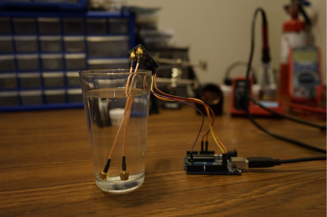
Figure 4. The Randle's Cell Testing Device measuring Impedance of an Aqueous Solution
Software
The AD5933 was calibrated and programmed using the popular Arduino IDE. The code was created following the AD5933 datasheet to ensure proper calibration and operation. Commands are written from the Arduino Uno, to the AD5933. Through the popularity of the Arduino IDE and our extensive documentation, we hope to ease the burden of datasheet synthesis and understanding of the AD5933 for future users. You can find our documented code on our GitHub
RESULTS AND CHALLENGES
We were able to construct an impedance testing circuit for $86 CAD using electrical components and parts sourced from major distributors operating at locations around the globe. Notably, we were able to measure the impedance of an aqueous solution, indicating the viability of our impedance circuit in monitoring electrochemical cells.
Table 1. Cost of Randle's Cell Testing Device

We were able to measure the impedance across a capacitive load to a high degree of accuracy. Measuring a known load, we were able to make impedance measurements within 0.02% error, operating in our target 10 kHz range.
Figure 5 is frequency sweep data we collected using the AD9533, and makes apparent the inverse relation between frequency and capacitance.

Figure 5. Frequency Sweep of a 1 nF Capacitive Load using the AD5933
As with the majority of integrated circuits, they come with extensive data sheets and require the user to have a thorough understanding of it’s function. Oftentimes, programming the IC requires a user to learn a coding language specifically made by the manufacturer. The process of reading through the datasheet and learning how to program the AD5933 was a significant challenge. This ended up taking much longer than we anticipated.
IMPACT
Impedance is ubiquitous, and its importance as a measurement technique spans many different fields and technologies. Although we fell short of our goals, we hope that our research can provide a basis for future teams to use when developing impedance-based tests. Through thorough documentation of our hardware and software suites, we hope that this expedites the speed of future projects with the AD5933 by Analog Devices. This work brings us a step closer to accessibly identifying VAD.
Future Directions
Although we have found an aptamer sequence specific to our needs, we are in the midst of legal consultation to determine the patents surrounding the aptamer. Once an aptamer has been selected, we need to verify its selectivity to RBP in blood samples. We then plan on investigating and testing the methods of immobilizing aptamers onto electrodes.
REFERENCES
De Pee, S., & Dary, O. (2002, September 01). Biochemical
Indicators of Vitamin A Deficiency: Serum Retinol and Serum
Retinol Binding Protein. Retrieved October 24, 2020, from
https://academic.oup.com/jn/article/132/9/2895S/4687694
Lee, S. J., Youn, B., Park, J. W., Niazi, J. H., Kim, Y. S., & Gu,
M. B. (2008). SsDNA Aptamer-Based Surface Plasmon Resonance
Biosensor for the Detection of Retinol Binding Protein 4 for the
Early Diagnosis of Type 2 Diabetes. Analytical Chemistry, 80(8),
2867-2873. doi:10.1021/ac800050a
Lim, C. (2014, April). Lecture 20: Warburg Impedance. Retrieved
from
https://ocw.mit.edu/courses/chemical-engineering/10-626-electrochemical-energy-systems-spring-2014/lecture-notes/MIT10_626S14_S11lec20.pdf
Mahmood, K., Samo, A. H., Jairamani, K. L., Ali, G., Talib, A., &
Qazmi, W. (2008). Serum retinol binding protein as an indicator of
vitamin A status in cirrhotic patients with night blindness. Saudi
journal of gastroenterology : official journal of the Saudi
Gastroenterology Association, 14(1), 7–11.
https://doi.org/10.4103/1319-3767.37794
Mazlan, N. S., Ramli, M. M., Abdullah, M. M., Halin, D. S., Isa,
S. S., Talip, L. F., . . . Murad, S. A. (n.d.). Interdigitated
electrodes as impedance and capacitance biosensors: A review
[Abstract]. AIP Conference Proceedings 1885, 020276 (2017).
doi:https://doi.org/10.1063/1.5002470
Tanumihardjo SA. Biomarkers of vitamin A status: what do they
mean? In: World Health Organization. Report: Priorities in the
assessment of vitamin A and iron status in populations, Panama
City, Panama, 15–17 September 2010. Geneva, World Health
Organization, 2012.
Şimşek, Ç.S., Teke, M. and Sezgintürk, M.K. (2014), An ITO Based
Disposable Biosensor for Ultrasensitive Analysis of Retinol
Binding Protein. Electroanalysis, 26: 328-339.
doi:10.1002/elan.201300443
Sommer, A. (2001). Vitamin A Deficiency. In eLS, (Ed.).
doi:10.1038/npg.els.0002106
Venkatraman, V. L., Reddy, R. K., Zhang, F., Evans, D., Ulrich,
B., & Prasad, S. (2009, April 1). Iridium oxide nanomonitors:
Clinical diagnostic devices for health monitoring systems.
Retrieved from https://doi.org/10.1016/j.bios.2009.03.029
Whitehead, R., Jr., Jr., Perrine, C., Mebrahtu, S., Dahal, P.,
Subedi, G.R. and Jefferds, M.E. (2015), Defining a vitamin A
deficiency cut‐off for retinol binding protein in Nepal children
6‐23 mo of age. The FASEB Journal, 29: 729.5.
doi:10.1096/fasebj.29.1_supplement.729.5


